

Hello, there!
Last post, I covered my assumptions of you and related recommendstions, the bridge ground wire, and 4-lead humbucker pickup wire orientation. In this post, I’ll discuss potentiometer basics, the three way toggle switch, and hopefully by the time I’m done wiring (and writing this), I’ll have enough of a guitar wired together to do a first test.
Potentiometer sounds to me like “potential meter” or “meter of potential”. As measure of potential. When applying this to electronics, it has to do with how much electric current is allowed through a switch. When you turn a volume knob left, you are lowering the potential power that can go from the sound generating device to the speakers. Photographed below (Fig 3) are the potentiometers I am wiring into my guitar.
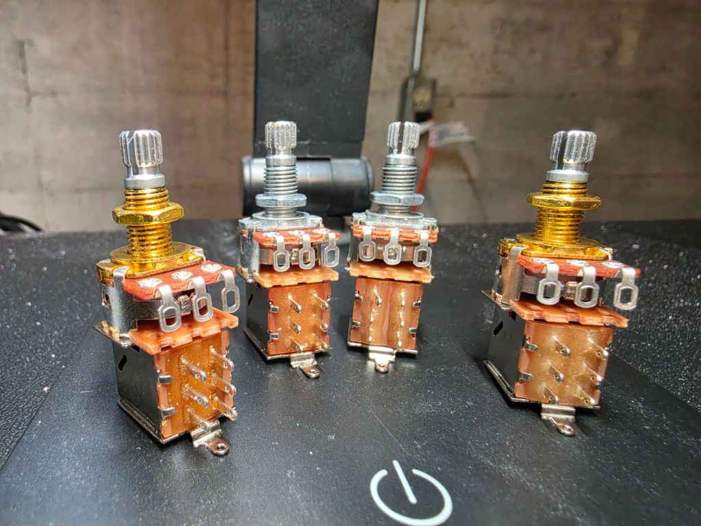
I have 2 “A” type pots and 2 “B” type pots. I’ll explain what that means below:
- “A” potentiometers – “Logarithmic” or “Audio” taper. Best used for volume controls. Can also be used for tone controls.
- “B” potentiometers – “Linear” taper. Best used for tone controls. Not recommended for volume.
- My recommendations here are based on my experience. YMMV.
All of my pots have a 500k resistance rating. Don’t worry too much about what that means. It’s important to remember 500k resistance pots are what work best for humbucking pickups. There are other values (1M for bass, 250k for single coil), but I won’t be covering them beyond that parenthetical.
Technically speaking, all the above photographed pots in Fig 3 will do is control the amount of electrical current allowed through a circuit in which they are wired. Which is why two of them need to be connected with a capacitor for tone control.
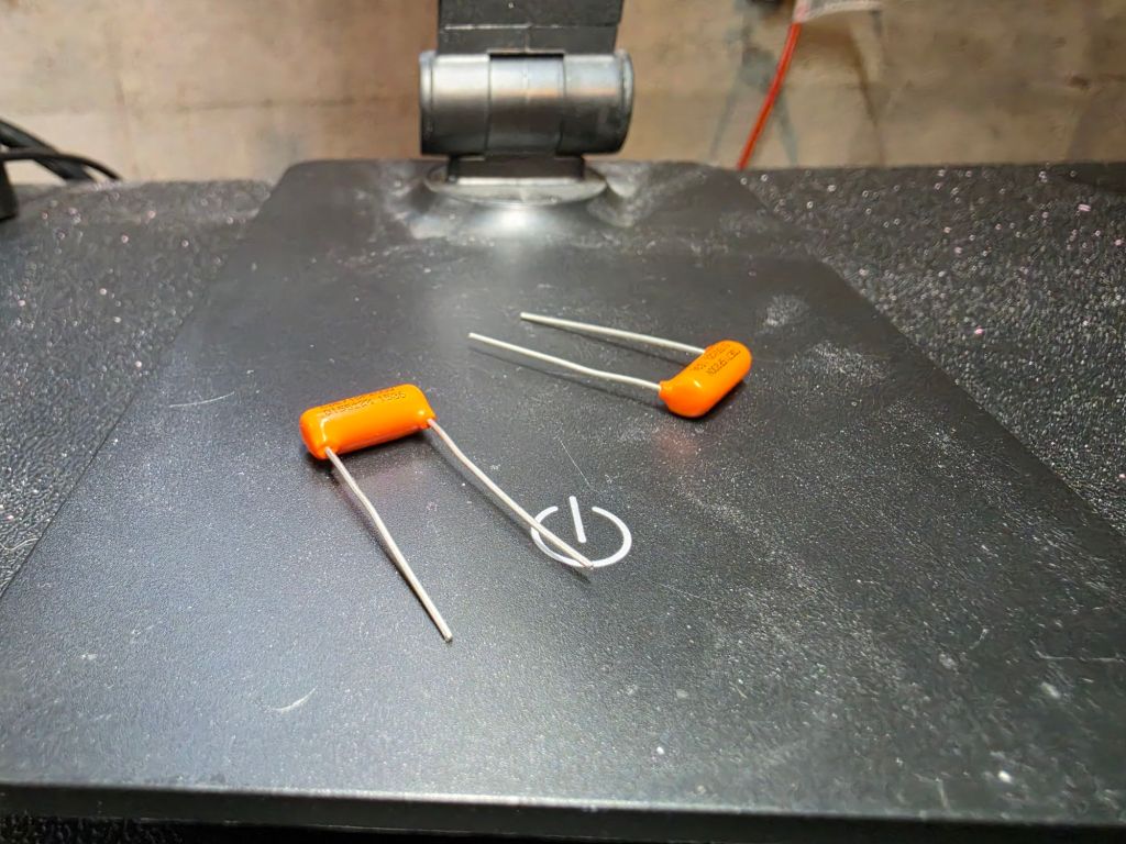
I don’t remember the specifics on these capacitors. Different values result in variations on treble and bass response. Do your own homework based on your desired applications and use your ears.
Now that we know the basics of potentiometers where the electric guitar is concerned, let’s talk about wiring.
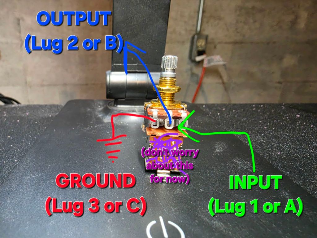
With what we have learned so far, we’d be able to solder a very basic guitar with one pickup and one volume potentiometer. Behold!
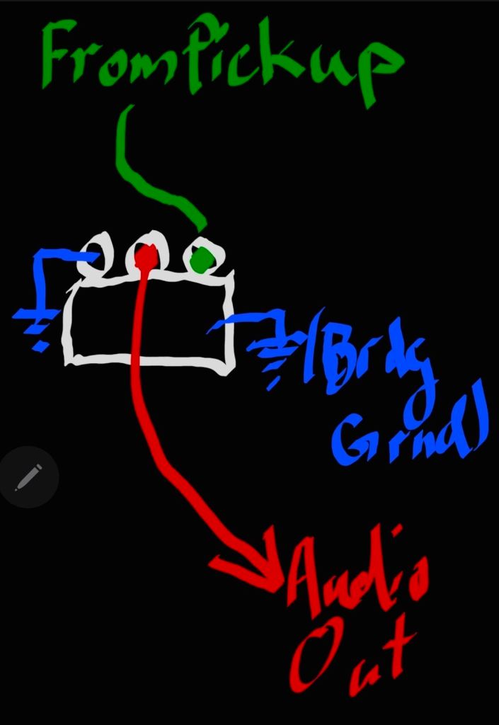
For tone pots, there are a lot of different ways to wire them. Do your homework and decide what works best for your needs. As for me, I’ll be wiring them the way they are wired in my EVH SA-126, which has the tone capacitor running from the output (Lug 2/B) to a ground on body of the potentiometer.
Now is where things get weird, because my specific wiring plan involves split coil and phase switching operations. Doing this requires either stand-alone switches or switches connected to the potentiometers. I opted for the latter. Mine are “double pull/double throw” style push/pull potentiometers. See Fig 7 below.
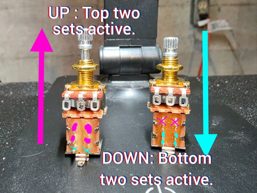
As I wrote, my potentiometers have a “Double Pull/Double Throw” or “DPDT” functionality. The purpose of such an item is to direct the flow of electricity in interesting ways. In my case, to deactivate one coil of a humbucker or to put them “in parallel” rather than having them remain “in series”. Deactivating a coil on a humbucking pickup reduces the sound sent to an amplifier as well as adds a hum (hence, humbucking). It can help produce an atmospheric “low-fi” effect compared to the full force of an in-series humbucker. In-series means the electric current is running through one coil of a humbucker at a time. In-parallel means the electricity is running through both at the same time. Having a switch that changes this is referred to as phase-switching. If you play high-gain metal and want to keep doing that, you may not find such functionality helpful. If you play what I refer to as “Yamaha guitar music” (the kinds of music where an electric guitar is clearly present, and removing it would take something away from the music but not completely shin-kick a song), you may find these functions helpful for quickly changing the vibe of the guitar sound.
I don’t know the full story on why specific lead wires on the humbuckers go where for my aforementioned desired result. As such, I am relying on a wiring diagram from guitarelectronics.com. It is below.
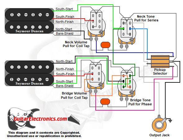
I’ll be wiring the capacitors a little bit differently, as I mentioned. Aside from that, I need to make sure my wire colors are going to the correct places in the potentiometers. For that, I need to reference Fig 2 from the previous post. Another thing to note (and this is what threw me for a long time with guitar wiring): the diagram is drawn in such a way that it is difficult to determine what goes where in some cases. This is why knowing how the equipment you have in hand works is so important. Hypothetical knowledge will break down under the weight of application if you’re not careful. In my case, I’ll be testing my wiring at every step of the way to ensure I’m getting the desired result. It’s kind of a non-computer version of “save early, save often”.
Now, let’s talk about the three-way switch. There are other methods to switch between pickups, but I’m using a three-way switch because of the kind of guitar I’m wiring. Photographs of my switch are below (Fig 9 & 10).
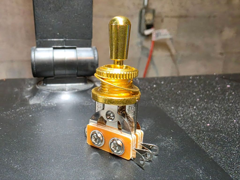
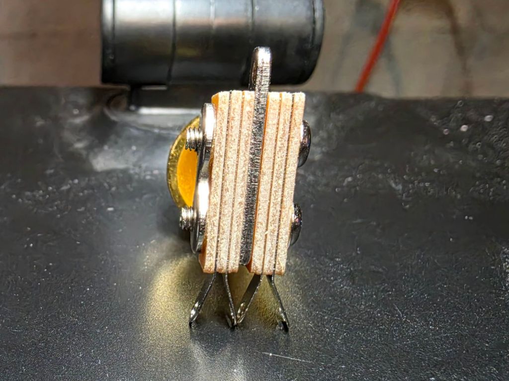
As we see in Fig 10, it looks a little bit like what’s in the diagram, but not completely. Below is a diagram of the switch I have (Fig 11).
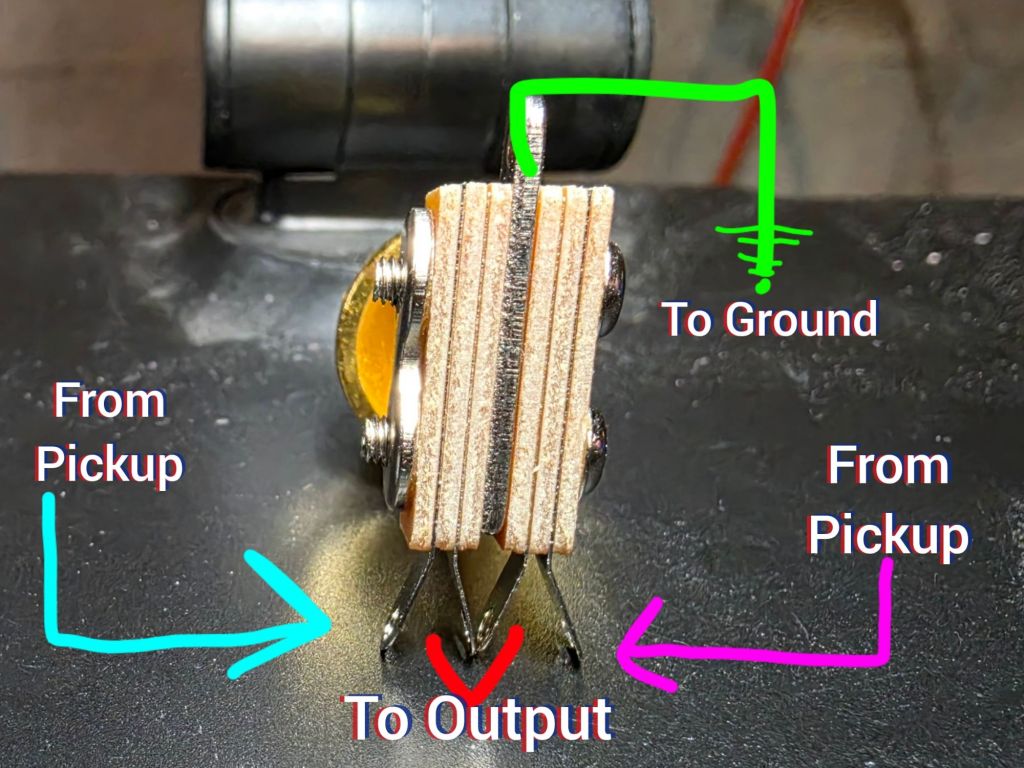
If you notice, it’s still not quite the same. For one, the ground appears to be on the opposite side of the pickup inputs. This is fine. However, the output needs both posts. Thankfully, the output can be split in twain. They are only lightly touching, and can be bent separate easily enough. One thing to remember, however, is to keep the inputs from the pickups and the now separate outputs separate (queue “Come Out And Play” by The Offspring). Something else to keep in mind is the orientation of the 3-way toggle switch in the body of the guitar. Make sure the switch is wired and positioned in a way that makes sense to you. Some folks like the classic way with the switch moving down for the neck pickup and up for the bridge, others like to do things different. I will be wiring it with an up/down orientation where the bridge is up and the neck is down.
Getting back to the wiring on the pickup end of things, I said earlier I need to reference Fig 2 from the previous post and transpose those wire colors to the diagram. Then I can begin a cycle of soldering and testing.
Please feel free to ask anything in the comments, and I’ll do my best to answer. Happy tone-chasing!

